FT290-R CTCSS Board
This page describes a home made CTCSS encoder board for my FT290. I dusted the Rig off towards the end of 2006 and soon realised that things had changed since I last used it on a repeater. Here in the UK, repeaters are more and more using CTCSS only access and this makes a rig like the FT290 useless for repeater operation.
I found a very nice CTCSS encoder using a PIC16C84 by Tony Hunt VK5AH. This is available on Tony's web site here. Thanks to Tony for sharing his work and making this project so much easier!
I altered the software for the PIC and did the necessary things to make it work in a PIC16F628. I quickly realised that I wanted to be able to set the tone frequency without opening up the rig, and as there are only 9 tones in use in the UK (10 with the special one for 70cms) I realised I could give the memory switch a dual function and use it to select the tone. This has worked out very well indeed and with a few more software tweeks to invert the logic of the switch, add a check to see if repeater shift is selected and remove the unwanted standard tones I have ended up with a very nice little board which fits in the FT290 in the place I assume the Yaesu optional tone board would have gone.
Here is a circuit diagram showing what is on the add-on board.
Here are the relevent bits of the FT290 circuit diagram. This is available elsewhere on the web for download.
This is the memory switch circuit
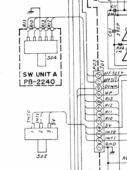
Most of the interface to the FT290 is done at socket J01 into which plugs plug P03. I soldered the wires to the board where the J01 connector pins are soldered. The 4 connections for the memory switch are taken from here, as are the +5V and 0V supply rails and the +ve and -ve repeater shift lines.
This is the microphone input plug
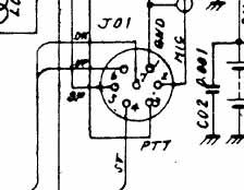
The PTT line comes in on pin 3 (on my rig is a green/white wire) and goes to the rear of the rig near the transmit / receive relay. It is ground to TX and has about 4.8V when in RX.
This is the tone input bit of the circuit.
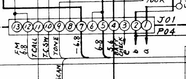
I have again soldered to the board where pin 9 from JO4 is connected. I didn't bother disconnecting any bits of the circuit around here as there seems to be no need.
The following table shows the connections to the FT290 and the wire colours I used.
| FT290 connection | Wire Colour | Useage | PIC pin |
| P03/JO1 pin 1 | Black | 0V | Vss (5) |
| P03/JO1 pin 4 | Green | +5V | Vdd (14) |
| P03/JO1 pin 5 | Brown | Mem Switch R10 | RB0 (6) |
| P03/JO1 pin 6 | Red | Mem Switch R11 | RB1 (7) |
| P03/JO1 pin 7 | Orange | Mem Switch R12 | RB2 (8) |
| P03/JO1 pin 8 | White | Mem Switch R13 | RB3 (9) |
| P03/JO1 pin 11 | Green | Offset- | RB5 (11) |
| P03/JO1 pin 12 | White | Offset+ | RB6 (12) |
| Mic plug pin 3 | Green/White | PTT | RB7 (13) |
| P04/J01 pin 9 | Purple | Tone | RA2 (1) |
This is a photo of my completed board. Built on vero-board, it's easily small enough to go in the rig. Note the 4HMz crystal is a large can version, which only just fits. Maplin (RIP), bless them, didn't have any of the small ones in stock.

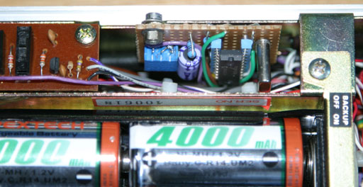
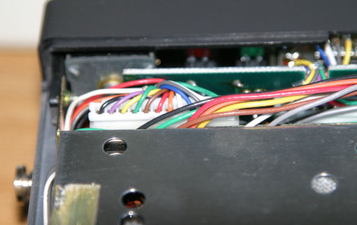
These two show how it fits inside the rig. The first is a view from the battery compartment and the second is from the other side. Note in the second photo, the coax which has replaced the poor telescopic whip, and that there is now a BNC connector on the front of the radio!

All the wires come through from the bottom past where the loudspeaker goes and on to where they connect to the rig. Most of them go to the connector shown in the next diagram.
Once installed the variable resistor needs adjusting to give the correct deviation. I had access to a Marconi RF test set, but without this trial and error would have to be used.
Here is the PIC16F628A source code for the project.
Here is the PIC16F628A hex file ready to go into a blank PIC.
Here is the circuit diagram in a word document.
David G4IRQ emailed me to say that he has completed this project and has suggested an alternative mounting location:
As my radio already had a Mutek front-end fitted in the space you used, I built it as small as I could using a small tantalum instead of an electrolytic and managed to squeeze it into the space between the back-up battery and the PCB immediately in front. I used ribbon cable to reduce the space needed for wiring and insulated the circuit with a dot of hot-glue and card. If I had to do the job again I would probably dispense with the IC socket to make the whole thing somewhat slimmer.
You are welcome to e-mail me with any comments if you like at mike at spikey-mike.com.
Home
